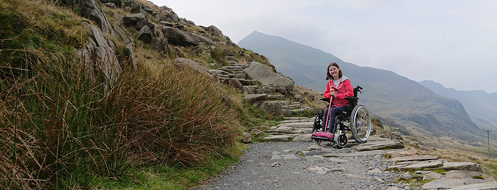
The Mountain Wheelchair project is no longer active. Seeing Ada stand up again for the first time, I turned my focus away from building the wheelchair to instead helping Ada to build up her health. She is still in a lot of pain and struggles on a daily basis, but... She has returned to school and achieved many A's/A*s in her GCSEs, takes "Outdoor Recreation" as one of her subjects, and is currently attending the Duke of Edinburgh Award. To top it off, she has since walked up the highest mountains in England, Wales, and Scotland!
As for myself, my energies are now going into delivering outdoor activities for Climb Wales where I get to help other young people (as well as adults) get out and enjoy the great outdoors. Primarily based in Snowdonia, North Wales, we work as mountain guides and also deliver a number of outdoor courses, such as:
Finally, a big thank you to everybody who supported the project. It gave Ada (and myself) hope, something to look forward to, when times were very dark.
Woohoo! It’s been a busy day in the shop. The spokes FINALLY arrived from China today and I managed to get the first wheel made.
It’s a motorised mountain wheelchair wheel!
First Motor Laced on a Mountain Wheelchair Wheel
Most of the the time was spent with a drill and file trying to get the separate parts to fit together, so although it’s a little bodged at the moment, it’s taken such a long time to get to this point that it feels like an important milestone.
I got Ada to control the throttle for a moment whilst I let the wheel roll on the floor. It’s much faster than it needs to be, but I think that will add to the fun of driving the wheelchair once it’s finished.
As well as the spokes, the “C Washers” which I had laser cut arrived today too and the guys at Microkerf did an excellent job. They’ve been extremely helpful and I’d definitely recommend them:
As I said in a previous post, I can’t be the only person who needs these washers so have listed them on eBay to try and raise some funds for the wheelchair.
E-Bike C Washers
Also currently on its way from the USA is a part which I hope will enable me to make the mountain wheelchair radio controlled – useful for testing purposes and driving it on/off trailers etc.
It’s also worth mentioning that Google doesn’t like us at the moment and we’re currently on page 3 for the search terms “mountain wheelchair”, however, on Bing at least, we are the very first result at the top of page 1.
So the 6 motors which will be used on the mountain wheelchair arrived this morning and I couldn’t help but open them up to take a look inside to make sure they were up to spec’.
Externally, the build quality looks great are the dimensions are perfect for the wheelchair. To get inside the motors you need a special tool usually, so I was really pleased when I undid the screws on the housing and it easily lifted away.
With the housing off, the first thing I noticed was that if I turn the axle, the motor spins much faster. 5 times faster to be precise. So that’s the first thing ticked; the motors will be able to spin at their optimal speed thus improving their efficiency, reducing the heat they generate, and all the while producing more torque.
Motor Windings
The second thing I noticed was that there are in fact 32 magnets with 16 pair poles, unlike many of the cheaper motors which have fewer magnets. This should result in a quieter motor with improved torque.
The motor also has a 20T winding (all of the copper wires which are wrapped around the “magnets”):
Mountain Wheelchair Custom Hub Motor Windings
These copper coils are what create an electromagnetic field when electricity is passed through them. As the “magnets” turn on and off in the right sequence, it turns the motor. Typically, the hub motors on ebikes have 6 to 10 windings (the amount of times the copper is wrapped around to create a magnet). A bike with 6 windings will travel at a higher speed; because there is less copper for the electricity to pass through it gets where it needs to be quicker. A 10 turn winding motor will therefore go slower because it takes more time for the electricity to pass through the coils. What this Chinese company have done for me is 20 turns which means that although the electricity will take twice as long (in simple terms) to pass through the coils, the resultant electromagnetic force will be twice as strong, thus resulting in a motor which has far more torque and travels at a speed which is more appropriate to a mountain going wheelchair.
Planetary Gears
Although I was happy with what I’d seen so far, I must admit I was a little disappointed with what I found when I extracted the motor from the housing; plastic Gears!
Mountain Wheelchair Custom Hub Motor Nylon Gears
Presumably the gears are made from ABS or Nylon and should last some time, but I can see myself having to service them in the future. At least I’ve got a 3D printer though so might be able to make the gears myself. I would have preferred steel(?) gears but I imagine these plastic ones will at least be quieter and cheaper to replace.
Freewheel Mechanism
Finally the other thing I wanted to have a look at was the freewheel mechanism. Bicycles are intended to roll down hill without the rider having to pedal constantly. For this to happen geared e-bike hub motors have an internal freewheel mechanism. For the mountain wheelchair, this presents a problem because when put into reverse, the motors would just spin freely without turning the wheels.
I’ve read about some people overcoming this problem by welding the freewheel mechanism, but the company that made these motors for me came up with a far more elegant solution. I believe it’s called a Woodruff Key?
Mountain Wheelchair Custom Hub Motor Wood Ruff Key
Verdict
So all in all, I’m a little sceptical about the plastic gears, but other than that I’m really happy with these motors; they’re lighter than direct drive hub motors, consume less power, they have internal temperature sensors but are less likely to overheat anyway, they’re well engineered, and importantly they should provide more than enough torque to get this wheelchair into the mountains.
In Other News
Now that I have both the hub motors and the wheel rims, I need to get the two things attached to each other. I’m not sure what, but something in the back of my mind tells me that it’s quite difficult to balance a rim on a hub. Add to that the fact that I don’t know what size spokes I need, I figured it was time to get some external help.
The first thing I did was ring West End Cycles in Colwyn Bay. The quote they provided over the phone, for all six wheels, was nearly £1,000! Just for putting some spokes on! Perhaps I’m just not appreciating how difficult it is?
I then rang Halfords in Colwyn Bay. They wanted £25 in labour per wheel, and although the guy on the phone was struggling to find the best price for spokes, he was able to find some which would cost about £35 per wheel. This puts the total quote from Halfords at £360.
Finally, I’ve got one more person to try who I discovered lives just around the corner from me. When I’m not so full of cold I’ll ask for him to have a look and take it from there.
The the post man knocked on the door this morning with several parcels for me. After opening them up and laying some of the parts on the floor I couldn’t help but do a little dance (much to Ada’s amusement):
Parts for Mountain Wheelchair Bogie
I realise this is just a couple of bike forks and wheel rims laid on the floor, but it feels like tangible evidence that it’s actually going to happen. I am actually getting ready to build the mountain wheelchair! Six wheels arrived in total, blue to Ada’s specification, and six forks. All of which are made of the same 6061-T6 aluminium that I plan to use for the rest of the wheelchair frame.
Motors have been ordered too
It’s also worth mentioning that the motors have been ordered too. I’m using e-bike hub motors, only one of which is able to push a grown adult up a hill on a bicycle. In theory then, shouldn’t six of them be more than ample? Unfortunately it’s not as simple as that; not only are these motors usually assisted by somebody pedalling, but they’re also designed to travel at speeds of about 30-40kph. Far too fast for a mountain climbing wheelchair! At a measly 3-5kph, which is about average for walking in the mountains, the motors would not be spinning in their optimal range and would likely overheat with dramatic effect.
To overcome this, I designed an internal cooling system for the motors. Basically, I planned to open up the motors (left image), weld some fins to the inside of the motors (middle image) and cut some holes in motor housing (right image). As the motor spins, the fins push air through the motor and help it to cool. I thought this was a good solution as it’s all being driven by the action of motors which are already spinning.
Originally I’d been planning to use 1500w 48v motors. I discovered that if I ran these motors at a lower voltage than they were rated for, then they would run cooler. However, at this speed and voltage, they would only have been about 20% efficient! I needed to find a better solution.
Custom Made Motors
After much research I was able to find a Chinese company that makes an e-bike hub motor with an internal 1:5 gear reduction ratio. This means that the motors will be spinning 5x faster than the wheels, allowing them to spin at a speed which is closer to their optimal range. Still, at the low speed of a mountain wheelchair, even these geared-reduction e-bike motors would get hot.
Geared Reduction Hub Motor
Luckily though, I was able to find a Chinese manufacturer that were prepared to do a custom winding on the motor magnets for me. Basically, with this custom winding, it means that the motor’s optimal speed range is much lower, and as a beneficial side-effect, they’ll have more torque. Perfect for climbing mountains!
Hub Motor Custom Winding
Another problem I had to overcome was that e-bike hub motors are designed to free-wheel. Imagine rolling down a hill on a bike, if the motors didn’t free wheel then you’d never be able to stop pedalling. A freewheel mechanism on the motor makes sense for a bicycle. It becomes a problem on a wheelchair because it means the motors won’t drive in reverse. Fortunately, the same manufacturer I’m buying the motors from are going to modify the freewheel mechanism so that the wheelchair can be driven in reverse. An added benefit of this is that as the wheelchair rolls down a hill/mountain, because the motors will still be turning, it means the power they produce can be transferred back into the batteries, thus extended battery life.
I haven’t looked at the math involved yet, but this does beg the question; when planning the battery capacity, would it be possible to set off from the bottom of the mountain with the intention of just having enough power to get to the top, and then expect that as you roll back down the mountain, you’ll have regenerated enough power to overcome and obstacles you encounter along the way?
Why not use Wheelchair Motors?
If I had more engineering experience, a better solution would probably have been to use wheelchair motors instead. After all, they’re designed to provide high torque at low speed without any modification. This would however have resulted in a far more complicated design for the frame. Using ebike hub motors is in my opinion a simple (elegant?) solution, which combined with bicycle forks should result in something that I can build myself, even with my limited experience. Or at least that’s the plan anyway.
Wheelchair Motor
Importing from China
Unsurprisingly, I’ve had to pay a little extra to get these motors made and ship them over from China, but I think it will be worth it in the long run. It is somewhat worrying ordering parts from China because there are many things that can happen to them along the way, such as hidden customs charges, loss and damage. That being said, my 3D printers were built using parts ordered from China and to date I’ve not experienced any problems. In fact, for the printers, it was cheaper to get the parts shipped from China than it was to buy them here in the UK, even with little things like a pack of screws!
What’s next?
The next big step will be to finish designing the mechanism which attaches the rocker to the bogie (the parts which connects all of the bicycle forks together), learn how to weld, and then start building the thing.
Before I can do that though, I need the motors to arrive and overcome any complications that arise when getting them to fit the wheel rims. Whilst I’m waiting for the motors to arrive my focus will be bringing the build-log up to date, fund-raising, and search engine optimisation. Oh, and finish building the life-size PVC model.
What a great start to the day; I awoke to the sound of the doorbell, dragged myself downstairs, and as I opened the front door was presented with a pleasant young man who, in his outstretched arm, was holding the new motor controller!
I hooked it up to the robot/wheelchair/thingummygubbin and was delighted to see the thing working post fire. Taking no chances this time, I welded another plate to the frame to act as a mount for the components and whilst I was at it, I designed and printed a clip-in holder for the radio transmitter which holds the antenna in the optimum angle:
New Motor Controller and RC Receiver Mount
I also finished designing and printing the chain guard for one side of the robot and applied a www.mountainwheelchair.com sticker. Hopefully this will prevent any little fingers being from being sliced off!
You’ll see in the picture above that I also have the robot hooked up to a laptop. After the fire I decided to spend a little extra on the motor controller and this one will not only provide more power to the motors but also provides the ability to fine tune the firmware and control power curves and a host of other things. Although at £100 it’s twice the price of the previous controller, I think it was money well spent. Especially if it doesn’t go up in a ball of flames.
Speaking of which, the burnt controller has been sent back to the good people at RobotShop.com who in turn have given me a refund.
In other news, I’m making good progress with the cowling, NextKarting have very kindly donated a lightweight go-cart seat, I’ve had considerable help designing and fabricating a skid-plate, and a new motor controller arrived for the smaller prototype today. I’ll post more details on each as things develop.
My father has spent all of his adult life as a chief engineer in the merchant navy and although he’s now retired, I’m sure he still retains lots of useful information which I could tap into. Yesterday he stopped by to drop off a birthday card and I introduced him to the project. I explained some of the difficulties I’d been having trying to find a balance between motor power and battery supply. He suggested using hydraulic motors.
With hydraulics, an electric motor powers a pump, which in turn drives oil at high pressure via flexible hoses to any number of hydraulic motors. The ship’s winches were powered in such a way.
Interestingly, shortly after he’d left I visited the endless-sphere forum where I’d been asking about how power is divided between motors and somebody else had also suggested using hydraulics.
This is a quick representation of what the system might look like:
Hydraulic motor
Before my father mentioned it, I didn’t know there was such a thing as a hydraulic motor so I have lots of research to do. However, it seems a good investment of time because:
Gear ratio between motor and pump can easily be adjusted to get the right balance of speed torque
Hydraulic pumps in general have more torque
The motor can be kept spinning at its optimum range and increase the lifetime of the motor.
One motor means one battery
Hydraulic motors are cheaper than electric motors
Hydraulic motors seem easier to service
It removes the need for complex sprockets and chains to drive the wheels
First of all then, I need to make sure that such a system would still give the ability to have forwards and reverse on independent sides so that the wheelchair can turn on the spot, and when required that power could be delivered to individual wheels…
Ultimately, I think it’s the batteries, or rather the power requirements, that are going to make or break this project.
My first calculations suggested that the wheelchair would need a 3 tonne battery, or in other words; this project is an impossible dream.
Employing a large dose of optimism I made some very arbitrary amendments to tailor the results of the calculations to make the project look possible but ever since it has been niggling away in the back of my mind.
Looking at it again, the Llanberis path has a distance of 7.23km and a total height gain of 0.966km (measurements taken from Ordnance Survey 1:25,000 map). Using trigonometry, we can work out that the average slope of the Llanberis path is 7.7 degrees:
Llanberis Path Gradient
To calculate this as a gradient, we simply divide the height by the length and then multiply by 100. (0.966 / 7.23) x 100 = 13.361%
Obviously the gradient of the path will be steeper in parts than others, but having this average should give us more accurate calculations.
As you double the weight though, the power requirement doubles. So a 200kg weight needs a 500w motor.
Obviously, as the power requirement for the motor increases, so does the power consumption and the weight of the required battery.
It’s clear then that power requirements, and therefore weight reduction, are going to become an important part of this project.
A 500w motor seems awfully small though when you consider that a child’s quad bike might have a 1,000w motor.
Looking at existing mobility scooters though, 500w seems very common. The only one I’ve seen which uses a larger 800w motor is this “All Terrain” Mobility Scooter:
“All Terrain” Wheelchair
Perhaps then a smaller motor would be sufficient? I guess there are currently too many unknowns to be able to find the right answer. With that in mind, I’m going to make a list of questions which need answering in order for me to get to the bottom of this:
Ultimately I want to know how powerful the motors need to be and which battery will provide that power?
In order to answer this question I need to know:
Weight of wheelchair – impossible to say without knowing the other values
Weight of passenger – 40kg approx, will need to get Ada on the scales
Weight of Motor – difficult to say without answering other questions first
Weight of Batteries – as above
Gradient of Path – 13.361% average
Steepest gradient likely to be incurred – need to take some measurements
Length of path – 7.23km to the top, 14.46km return.
How is power distributed between the motors – If six motors produce 500w each, does that mean you have 3,000w power?
If a 500w motor needs 30 amps to get up the hill, does that mean that the six motors need 180 amps (6 x 30) or does it mean that because there are six motors all doing the work they don’t need to draw as much power and therefore they have a combined power requirement of 30 amps?
On top of this I’m also going to need to know the power requirements of other devices, such as lights, battery indicators, linear actuators/hydraulics, any software controllers that might be on board, motor controllers etc.
As you can see, most of this can’t yet be answered so for the moment I’m going to concentrate on question 8 and 9. They seem like they shouldn’t bee too difficult to find the answers to and I expect they will influence the outcomes of the other questions too.
So the other day I estimated that the wheelchair would need to be driven by six 3,000 watt motors. At a constant gradient of 40 degrees, to do the 18 mile round trip, the 4QD calculator suggested the motor would have a constant draw of approximately 65 Ampheres.
I have in my shed a very large 12v 120AH leisure battery which I use to power an electric outboard motor on a canoe. The 120AH rating means that with a 6 Amp draw, the battery provided 12v for 20 hours.
With the 65 amp draw of the 3000w motor, this battery would last 1.8 hours (120 ÷ 65). Let’s say it took 5 hours to reach the top, then you would need 3 of these batteries.
Of course, this is only for 12 volts. For 48 volts we’d need to multiply this number by 4. 4 x 3 = 12.
That’s 12 very heavy caravan batteries. At a guess, I’d say my 120AH battery weighs about 30kg. So overall, that’s a weight of 360kg just for the batteries.
But… Because I want to use 6 motors, does that mean I have to multiply this number by 6? If it does, then it would mean that the batteries weighed over 2 tonnes!!!
And of course, if you’re dragging a two tonne battery up the mountain then the power requirements of the motors increase and then so do the battery requirements. Perhaps then it isn’t possible, and this is why it appears something like this doesn’t already exist.
How about looking at other battery solutions?
I came across a 1.2v 500ah battery which weighs 15.9kg dry. To make a 48v battery, you would need 40 of these. 40*15.9. That’s 636kg for one motor and that’s without the battery fluid. You’d then need to multiply this by 6 which is nearly 4 tonnes and that’s before adding battery fluid.
It was starting to look like a bit of a pipe dream so I got out my map and actually measured the distance to the top of Snowdon rather than relying on secondary information. The distance to the top of Snowdon (On the Llanberis Path) is just over 7km, so a 14km round trip, which is far less than the 18 miles that I’d been using up until now. The internet lied!!!
I’ve also made a very basic estimation of the Llanberis path’s gradient. I had originally been using a value of 30 but keeping in mind that I’m sat at my desk and not out in the field, I’ve estimated it to be more like 10 degrees.
So if I took these new values, slowed down both the the acceleration and top speed, and gave the calculator what could be an unrealistic weight of 200kg, the current draw comes down to 20 Amperes. This would mean that 4 of the caravan batteries (120kg in total) in my shed would be able to get us to the top.
The problem now is that I don’t really know if I then need to multiply this by 6, so that each motor has the same battery pack.
I think the answer isn’t going to be as simple as this.
With 6 motors, individually they won’t need to draw as much power from the motors because they’ll be sharing the load. Imagine trying to push a car by yourself. Then imagine how much easier it would be if you had five more people to help.
Using this analogy, I suppose the same amount of force is required to push a car no matter how many people are pushing. Perhaps it’s the same for the motors? It doesn’t matter how many motors you use, the amount of current drawn will be the same.
I don’t know enough about electricity to be able to say if this is the case, and I imagine it’s not as linear as this, but it does at least sound logical. If this is case then it would mean that 120kg battery (or thereabouts) might get the wheelchair to the top of Snowdon. 120kg still sounds like a lot, but really it’s just four caravan batteries and this to me sounds doable. It is at least far more doable than a 3 tonne battery.
Moving forward, it’s clear that I don’t have the required underpinning knowledge to make these kinds of calculations and I think it’s therefore time to ask for some expert advice.
I think I might also have to stop feeding Ada! Or as mum suggested, ask Elon Musk for help.
Over the weekend Ada and I went into Colwyn Bay KTM and Honda to look at quad bike wheels and see what inspiration could be drawn. Originally I had in my mind that the wheelchair was going to use fat, chunky quad bike wheels to provide better grip on the wet rocks, however, for some time I’ve been thinking that a thinner 12″ wheel would probably do the job. Low-and-behold as we walked into KTM I was instantly drawn to this 12″ wheel on the back of a pit bike.
12″ Pit Bike Wheel
It somehow seems smaller in the photos but I think it’s ideal. Without measuring the steps at the top of Snowdon and doing a lot more testing I won’t know for certain if 12″ is the right size but they do help to keep the overall weight down, will mean the wheelchair is more likely to fit through narrow gates and stair cases, and will look less menacing to mountain walkers.
12″ wheels with 3000w motors built into the hubs are also readily available:
However, I am more drawn to the 13″ wheel which is capable of producing 225Nm torque, whereas the 12″ only 182Nm. Another useful feature of the 13″ wheel is that the wheel rim easily detaches from the hub. At £400 each (and I think we’ll need six), the motors are probably going to be the most expensive part of this build. If a rim gets damaged, it means that you can just replace the rim without having to replace the whole motor. It also means you can easily change the tyres so that you could have a set of both off-road and road going tyres.
These 13″ wheels take a 130/60-13 tyre such as this Maxxis M6024:
Combined, the wheel and tyre would have an outside diameter of 19″ and a width of 5″.
This means that if the wheels were touching each other, the shortest possible length of a 6 wheeled vehicle is nearly 60″. This size needs to be increased though to allow the rocker bogie mechanism to work. I don’t yet know if a 19″ wheel will be suitable to get up the steps at the top of Snowdon but thinking about the overall size of the wheelchair, I certainly don’t want to go any bigger than this if possible. Generally speaking though, a rocker bogie mechanism is capable of overcoming obstacles which are twice the wheel height. For a 19″ wheel that’s 38″, or three and a half feet. Imagine seeing a wheelchair drive over a 3 1/2 foot tall obstacle!!!
Taking the measurements of these wheels and combining them with the measurements of Ada’s current wheelchair, the following is a scale drawing of what the finished wheelchair might look like.
Scale Drawing
Although this is a very rough concept and room needs to be made for the differential and batteries, and at the moment the positioning of Ada’s feet will dictate the maximum size of obstacle it can overcome, it does at least give some sense of scale and is a better representation than the current working prototype.
I’ve been doing some research into power requirements and to be honest a lot of the math such as calculating torque curves is going over my head. I’m sure I could get a grasp of it if I really applied myself but I think this would require considerable effort to develop the required underpinning knowledge. Fortunately I have been able to find some very useful online tools that help to make these calculations easier.
Before I go into them though, I want to share some of my sanity checks.
A typical “powerful” child’s quad bike uses a single 1000w motor. The motor is connected to the rear axle using a chain. Being able to adjust top speed/torque by changing gear ratios would be advantageous. This 1000w quad bike is faster than our needs so that same motor could be geared to give low speed torque instead.
Keeping in mind that in the video above the rider is on a flat even surface and we don’t see how long it’s taken to accelerate to this speed, it does at least give some idea of what a 1000w motor running off a 48v battery is capable of and gives us a reference point for future calculations.
The bike in the following video uses a single 3000w motor and is clearly capable to carrying the rider up hills at significant speed.
A typical Land Rover winch might have a 3,500w motor.
In all of these examples though, the power is coming from just one motor. If I stick to the rocker bogie design then the wheelchair will have six motors, so six times more power (Although it’s obviously not as simple as this as not all wheels will have equal traction etc). Given this EXTREMELY BASIC research, it would appear that 3000w or similar motor might be up to the job.
1. Vehicle Speed. The wheelchair needs to be able to move at a brisk walking speed of 5kph.
2.Vehicle Weight. Impossible to say at the moment. just to get a rough idea, lets go with the combined average weight of 4 UK adults. 77 x 4 = 308kg.
3.Passengers. 1 child.
4.Nominal Battery voltage. The higher the voltage given to the motor, the higher its torque. To keep the weight of the wheelchair down, I want to try and avoid going over 48v if possible and prefer to keep it even lower.
5.Weight of one battery. Difficult to say as I don’t yet know which batteries I’ll be using. For the moment I won’t add any weight here and just count it as already having been included in the overall weight.
6.Motor current on level ground. This is a difficult one as you usually cannot guess or measure it until after you’ve finished making the vehicle. The website recommends that if you’re unsure just use their value of 10 as it’s likely to be a fairly small part of the total.
7.Hill climbing ability. A rocker bogie vehicle will usually topple over on a gradient of more than 45 degrees. Ideally I’d go and measure the gradient of the Llanberis Path but for the moment I’ll use 30 degrees as an example. This is a gradient of about 55%.
8.Length of hill. It’s an 18 mile return journey but it won’t need the peak current for all of the time. If I said 15 miles then I think this is quite generous. 15 miles is 24km.
9.Acceleration. Acceleration time isn’t too important in terms of how long does it take to reach top speed. More importantly though is when it’s climbing over obstacles, how quickly can power be transferred to each wheel. I’ll experiment with this value to see what happens.
The results:
Data Input
Power Requirements
Given the values above, the calculator has suggested a motor of 2,500w. Given the earlier Youtube references as a sanity check, this seems OK.
In addition to this, changing the voltage supply and time to accelerate doesn’t make any difference to the output of the calculator in terms of which motor is needed.
The calculator doesn’t take into consideration things like friction, uneven surfaces, and weather etc, however it does assume that one motor will be carrying the full weight of the vehicle. In light of this, a 2,500w motor will probably be OK.
When I start shopping around I will consider 3000, 4000, and 5000 watt motors and if the cost isn’t too prohibitive will invest in bigger motors. However, for the moment at least I have a rough idea.
I like the simplicity of being able to a buy a motor which is already embedded into the hub of a wheel as it will make building the wheelchair far simpler. Although UK suppliers have been difficult to find, I have found this Chinese manufacturer which has a huge range to choose from.
There is also a 43 page forum thread started by the manufacturer on Endless-sphere.com. I’ve only glanced at the discussion but comments on there seem positive. Both the Endless Sphere forum and the Chinese manufacturer look a good place to obtain some advice.
Having said this though, despite the complications of mounting a motor separately to the wheels, it does give the advantage of being able to change gear ratios and makes it possible to work with local manufacturers.
One of the biggest unknowns at the moment is which motors are going to be used in the final wheelchair.
The problem is that my background is in computing not engineering and I don’t know much about motors. As an experienced walker though I can make some calculations about speed.
The average healthy person walks in the mountains at a speed of 4km per hour (2.5 mph) so there isn’t much need for the wheelchair to go any faster than this. To work out what speed the motors need to turn, I’m going to use a 12″ (30cm) wheel as an example. A 12″ wheel has a circumference of nearly 1m. To travel 4km then it would require 4,000 rotations. This tells us that this wheel would need to rotate at a speed of 4,000 rotations per hour, or 66.66 rotations per minute. If we rounded this up to 67RPM we have an idea of what speed a 12″ wheel needs to rotate in order to travel at a walking pace.
This example though presumes that the wheel turns at the same speed of the motor and doesn’t take gear ratios into account. However, even with this simplified example it becomes clear that the motor doesn’t need to operate at high speeds. What’s going to be more important is torque, but more on this in a moment.
Providing power to the motors is also a current unknown. To complete the 18 mile journey to the top of Snowdon and back at 4kmph would take about 7.5 hours (without stops). This would mean that the batteries would need to be able to supply constant power to the motors for an absolute minimum of 7.5 hours, although this doesn’t take into consideration things like terrain, angle of inclination, or wheel spinning/slipping.
Another consideration is the battery voltage. It’s a lot more complicated than this but in very general terms, the higher the voltage rating of a motor, the higher the torque. Also, as a battery’s ability to supply a higher voltage over a longer period of time increases, its size and weight also increase.
I don’t yet know what calculations I need to perform, but, I don’t think a 12v battery (similar to what you’d find in a car) will be big enough. To get enough torque out of the motors, I’d guess that we’d need at least 36 volts (3 car batteries).
If the final design employs a rocker bogie mechanism then it will likely need 6 motors (one for each wheel). 3 car batteries for each motor (18 car batteries!!!) is clearly out of the question. I think it will most likely either use one battery for the whole system, or two batteries so that there is one for each side. This could be a 48v battery overall, or 2 x 24v batteries.
I don’t think it’s possible to decide on a battery until we know the power requirements of the motor though, which brings me back tot he topic of this post.
Motors
Motors are powered by magnetic fields. These magnetic fields are created by passing current through a wire. The stronger the current, the stronger the magnetic field. So as I said above, in very general terms, the higher the voltage rating of a motor, the more torque it has.
There are different types of motors such as brushed, brushless and servo motors amongst others.
According to sparkfun.com, brushed motors have the advantage of being simple to control, have excellent torque at low RPM and are inexpensive to manufacture. They sound perfect for our needs. The disadvantages of brushed motors are that the brushes can wear out over time, they generate electromagnetic noise and are usually limited in speed due to brush heating. As mentioned above though, speed isn’t an issue for us and brushes can be replaced. Noise could be an issue though as it’s going to be important not to upset other hill walkers.
Brushless motors are becoming more and more popular as they are reliable, efficient, produce high speeds, are mass produced and easy to find. They are however difficult to control without a specialised controller, and importantly they require a low starting load.
In comparison then, brushed motors are better for low speed torque, whereas brushless motors are better for high speed where torque isn’t a concern. Of the two it’s clear that a brushed motor is the more suitable.
The motor manufacturer MAHLE sell 24v DC motors with a power rating up to 3,5 kW. These motors are used in winches and the like. If they can pull a Landrover then they shouldn’t have difficulty pulling a wheelchair. However MAHLE also sell an AC induction motor which is specially designed for low-voltage applications and for use in electric vehicles. Although they use alternating current, they will still run off a direct current battery with the use of an ECU which converts DC to AC. MAHLE’s 24v AMT has a power rating of 5kw. Although I still don’t know what power rating is needed, just to give some context a child’s electric quad bike typically uses a 1kw motor.
MAHLE AC Induction Motor
1kw Quad Bike
In summary, this feels like progress towards choosing a motor and it seems the first step is to calculate torque requirements and then research AC induction motors.