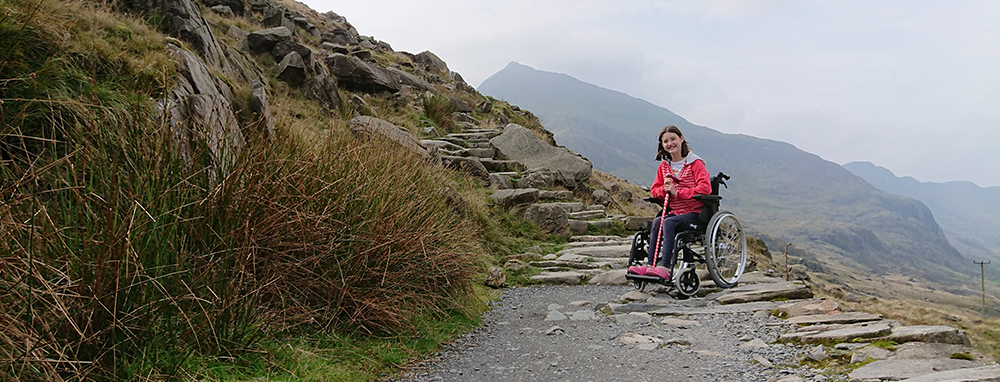
The Mountain Wheelchair project is no longer active. Seeing Ada stand up again for the first time, I turned my focus away from building the wheelchair to instead helping Ada to build up her health. She is still in a lot of pain and struggles on a daily basis, but... She has returned to school and achieved many A's/A*s in her GCSEs, takes "Outdoor Recreation" as one of her subjects, and is currently attending the Duke of Edinburgh Award. To top it off, she has since walked up the highest mountains in England, Wales, and Scotland!
As for myself, my energies are now going into delivering outdoor activities for Climb Wales where I get to help other young people (as well as adults) get out and enjoy the great outdoors. Primarily based in Snowdonia, North Wales, we work as mountain guides and also deliver a number of outdoor courses, such as:
Finally, a big thank you to everybody who supported the project. It gave Ada (and myself) hope, something to look forward to, when times were very dark.
Recently, whilst building the larger prototype, one of the things that has caused delay is one of 3D printers being busy with other projects and the other one completely out of action. I spent most of last week stripping it down and rebuilding it and gave the working printer an overhaul whilst I was at it. It was a huge relief once both printers were up and running again and the quality of the prints are now better than ever.
Although it works, the syringes aren’t perfect and small air bubbles are being drawn in. As a proof of concept though, it’s great, and I think it has more potential than both the differential gears and the differential bar. The reasons being that there is less wear and tear on the hydraulics (than the other proposed methods) and therefore less maintenance with increased reliability, but also it has a dampening affect which should result in smoother ride for Ada.
Few! Some progress was made today as I’ve just finished working out the details of how I’m going to mount a pair of syringes to the frame of the small prototype to act as a hydraulic differential. Just need to find a time where the 3D printers aren’t busy with other projects now :S
Hydraulic Syringe Mount
In other news, everything is sorted, booked and dotted lines signed for taking the engineering students up Snowdon next Thursday to take some measurements! Just need to keep fingers crossed for some mild weather.
Syringes arrived in the post yesterday so last thing at night I made a quick bodge using some cable insulation and a glue-gun. Even with water it actually works quite well:
The ball joints work!!! …sort of! (That’s becoming a bit of a catch-phrase!)
The ball joints have quite a small “turning circle” and I’ve had to loosen the nuts on the threaded bar to allow the ball joints a little more freedom. There are ways to overcome this though and this will be my next update. Ultimately though (and bearing in mind I’ve done no research yet) I’m leaning towards hydraulics.
Last night I said the next thing I was going to do was explore ball joints, but as I was sat at a desk in work with no access to the physical parts or CAD software, I started thinking about hydraulics again and drew a quick sketch:
Hydraulic Differential
As I’ve mentioned, I think hydraulics have excellent potential. My only concern is that essentially the rocker bogie mechanism is inspired by NASA’s Mars rovers which employ a differential bar mechanism. Other methods I’ve seen use differential gears (and is the current method on the working prototype). I’ve never seen hydraulics being used for this purpose. Is this because it doesn’t work, or is it because nobody else has thought of it?
I know very little about hydraulics, much like all the other areas of this project ( :) ), but I can imagine that there’s likely to be some lag in the system as oil is pumped around and it won’t be as responsive as a geared system. Mind you this might not necessarily be a bad thing as it could potentially have a dampening effect which reduces the wobble in the driver’s chair even more?
It’s definitely worth exploring because if it does work, it presents far more freedom to position parts and the only part which needs to travel through the main body of the wheelchair is a flexible hose which connects the hydraulic cylinders on each side. This in turn gives you greater freedom to position seats, motors and batteries and the like as you’re note having to accommodate gears or bars but instead a flexible hose.
I also imagine that a hydraulic system will incur far less wear-and-tear than a geared differential, and less impact than a ball-jointed differential bar mechanism.
There other potential uses for hydraulics too but not knowing enough about hydraulics, a linear actuator might be better suited…
When overcoming obstacles such as steps, the front wheels are pushed into the step and with the traction created with all six wheels, the front wheels “drive” up the step. The problem is that the front wheels don’t always get traction.
To overcome this, you could use hydraulics (or a linear actuator), or perhaps even just the drive from the middle wheels, to lift the front wheels off the ground before approaching the obstacle:
Front Wheels Lifted to Approach Obstacle
This would greatly increase the chances of overcoming an obstacle. Without having done any research though, I imagine this would mean having to add the wight and power of some kind of hydraulic controller. Linear actuators on the other hand are just driven by electric motors so could use the power of the batteries (and perhaps even the motors) already attached. it is possible though that if you cut power to all of the wheels, then just delivered power to the middle wheels that the front wheels would automatically lift off the ground.
Another benefit of being able to do this is that it gives you a shorter wheelbase making it possible to turn in more confined spaces. It does however look a little unbalanced with the front wheels off the ground but the lifting up the middle wheel retains balance whilst still giving a shorter wheelbase:
I arrived home from work today to find that a number of parcels had been delivered by the postman. Amongst the parcels were metal ball joints for the rocker bogie system (more on this in another post) and the final components I needed to make a radio transmitter/receiver.
Essentially, this is a radio control with a forwards and backwards button for the each side of the vehicle. Once built into the prototype it should allow for a greater range of testing.
Getting this working has been extremely satisfying and I’m trying to put my finger on why that is. I guess that as I child I’d always wanted a radio controlled car and now as an adult I’ve built Ada’s little brother Eric a radio controlled lorry by commandeering a remote from another toy. This was also the case for the current working prototype. I guess that being able to make one from scratch just opens up a whole new world of opportunities for letting out the big kid in me.
In other news, it’s been a very productive day all around. The engineering students have started building their own prototypes (more on this later too) and being in class with them gave me the opportunity to splurge out all of the ideas that have been running around my mind.
I also had a chance meeting with another lecturer who suggested using hydraulics to equalise the rockers. I think this likely has great potential and needs to be looked into further. One of the advantages that I would expect is less wear and tear on moving parts and ultimately a more reliable wheelchair. I’m not sure how I’ll make a prototype, syringes maybe(?), but seeing as the metal ball joints arrived in the post today I’ll explore those first…
Although I’ve been doing lots of research this week, it felt like not much tangible progress had been made. Frustrated, I quickly mocked up and printed a working differential bar which uses ball joints.
As you can see in this video, it works, sort of:
Movement is restricted by the dimensions of the system, so I’d need to work out how far the rockers need to move and calculate the required size of the ball joints accordingly. Also, this prototype is unusable because the ball joints pop out far too easily, although this is mostly because they are a very rough, plastic print. As discussed previously, the full size version could use Land Rover ball joints.
For the current prototype I’ve ordered these ball joints which are used in Radio Controlled Cars and some M3 threaded bar.
M3 Threaded Bar
RC Ball Joints
These ball joints will help, but I can still foresee problems. Of the three solutions I’ve found though I do think using ball joints is the best because it provides the most freedom to change the position of different elements, can be easily embedded within the frame, and can be built using off-the-shelf parts.
I have discussed previously the problems with the existing geared differential and after last night posting an update on possible solutions, I have made a working prototype of the linear bearing method:
I’m actually very surprised how well it works. There are some weak points in the joints but this mostly related to it being a very rough prototype and could easily be overcome. As I say though, it’s actually working far better than I thought it would.
Still, I like the idea of using ball joints because I could just buy one off the shelf and this would save complications in manufacturing and make them easier to replace if they fail.
In fact, purchasing a pair of automotive Sway bar End Links, or Stabilizer Bar Connecting Rods would vastly reduce the amount of work that needs to be done. They’re also tried and tested on road-going cars so should be perfect for this application.
The first uses two linear bearings with a swivel joint between them:
The second uses an armature with a ball-joint at each end:
The advantages of the linear bearing mechanism are that the differential bar can be close to the rocker mechanism, whereas in the ball-joint method there needs to be enough space between the differential bar and the rocker for the ball-joint armature to have enough room to swing. However, if using the linear bearing mechanism then the bearings will need constant maintenance, the rods would need greasing, and at the moment, I haven’t thought of a way to effectively enclose the mechanism to stop dirt getting into the grease. The linear bearing method also looks like it could create a lot of friction whereas the ball-joint method appears to move more freely.
I have some 8mm diameter steel rods and 8mm linear bearings lying around that I can make use of to see if this solution works.
As mentioned previously, the existing rocker bogie design is working brilliantly:
…however, I do forsee that it’s going to cause problems down the line. For one, with the weight of the vehicle and the sort of terrain it will be going over, the force of every single bump will be transferred to this differential. Over time I think a geared design would need a lot of maintenance to be reliable. Not only this but the differential has to be placed in line with the pivot point of the rocker-bogie. This means that the seat, batteries and motors etc all have to fit around the differential. The differential takes precedence.
To overcome this I’ve been developing a differential bar which will be mounted at the back of the wheelchair so it fits around the chair and batteries, and not the other way around. This video shows the initial concept.
The idea is simple; the bar is fixed in a central point and to the two rockers. As one rocker moves up, the differential bar pivots and pushes the other rocker down.
Unfortunately it’s not as simple as I’d first thought though. As you can see in the videos, the differential bar moves through the rockers because it has a fixed length.
To overcome this, I thought about a sliding mechanism that could sit between the rockers and the differential bar. In this video I’ve added a chequered pattern to the differential bar to make it easier to see that the blue parts attached to the rockers slide along the differential.
Unfortunately, this wouldn’t work either and I’ve created another video to demonstrate why.
In this video, you can see that the differential wouldn’t be able to have a fixed point on the rockers. To emphasise this the ends of the differential are highlighted with blue arrows and I’ve added red arrows to the rockers. As the rockers move up and down, you’ll see that the red arrows move backwards and forwards. This highlights the fact that it wouldn’t be possible to attach the differential directly to the rockers.
To make it easier to visualise what’s going on and try to find a solution I’ve made the following video.
It’s clear to see in this video that the rocker and the differential pass further through each other as they become horizontal but somehow their connection needs to follow the dotted line in order to be effective.
To overcome this problem the first thing that’s obvious is that the two parts shouldn’t be slicing through each other to begin with. By shifting the white part upwards, the two parts no longer intersect.
The next task then is to develop some kind of sliding mechanism that will sit between the two, queue pencil sketches on the backs of envelopes covered in coffee stains!
Initial Design Ideas
Whatever solution I come up with, just like the geared differential, it’s going to be under a lot of force so needs to not create a weak link in the system. Rather than talk about all of my scrapped ideas, I’ll wait until I’ve got a working solution and update but I expect it will involve a couple of ball joints.