It’s Alive, Oh No, It Died

So today I discovered that you can’t weld aluminium to steel, no matter how hard you try, and for a brief moment my larger prototype was alive, until the aluminium/steel weld failed:

Will need to find another solution for the motor mount and it looks like the chains might need a link taking out but it’s getting there.

Our Robot Wars Entry

Just a quick update; I’ve sat and worked out how I’m going to mount the wheels and sprockets for the large scale prototype and think I’ll be able to 3D print the parts I need.

When I showed Ada the wheels earlier, she immediately asked if we could paint them purple. So with a touch of Purple, here’s a scale drawing of what the next prototype will look like:

Ada’s been told that if she sits on top with a hammer then we can enter her into Robot Wars!

Internet Shopping Works… Sort of!

I love the convenience of internet shopping and being able to come home from work to find that goodies have been delivered.

Today I came home to find this lot had arrived:

As you can see, I’m planning a larger scale prototype. Just something simple to begin with; a solid frame, no suspension, six wheels, two motors.

On Sunday (day before yesterday) it was my birthday, and I had asked the kind birthday pixies to bring me 6 wheels and two motors.

Now as I said, internet shopping is great, sort of…

One ebay seller sent the wrong motors (120w instead of 300w), and another only sent one piece of mild steel box section instead of the three that I’d paid for. In addition to this, mummy (Ada’s) bought me 12 wheels instead of 6!

So whilst internet shopping is great, it’s not the same as walking into a shop and getting exactly what you need. Nonetheless, as I sit here writing this, more goodies are on their way and I now have two spare wheels to play with and four more to make Ada’s brothers a go-cart. Woop!

Differential Bar with Ball Joints

Although I’ve been doing lots of research this week, it felt like not much tangible progress had been made. Frustrated, I quickly mocked up and printed a working differential bar which uses ball joints.

As you can see in this video, it works, sort of:

Movement is restricted by the dimensions of the system, so I’d need to work out how far the rockers need to move and calculate the required size of the ball joints accordingly. Also, this prototype is unusable because the ball joints pop out far too easily, although this is mostly because they are a very rough, plastic print. As discussed previously, the full size version could use Land Rover ball joints.

For the current prototype I’ve ordered these ball joints which are used in Radio Controlled Cars and some M3 threaded bar.

M3 Threaded Bar

M3 Threaded Bar

RC Ball Joints

RC Ball Joints

These ball joints will help, but I can still foresee problems. Of the three solutions I’ve found though I do think using ball joints is the best because it provides the most freedom to change the position of different elements, can be easily embedded within the frame, and can be built using off-the-shelf parts.

Differential Bar Working Prototype

I have discussed previously the problems with the existing geared differential and after last night posting an update on possible solutions, I have made a working prototype of the linear bearing method:

I’m actually very surprised how well it works. There are some weak points in the joints but this mostly related to it being a very rough prototype and could easily be overcome. As I say though, it’s actually working far better than I thought it would.

Still, I like the idea of using ball joints because I could just buy one off the shelf and this would save complications in manufacturing and make them easier to replace if they fail.

In fact, purchasing a pair of automotive Sway bar End Links, or Stabilizer Bar Connecting Rods would vastly reduce the amount of work that needs to be done. They’re also tried and tested on road-going cars so should be perfect for this application.

Idea for a quick mockup

I’ve been spending a lot of time thinking about motors and really like the simplicity of having a motor embedded in the hub wheels.

E-Bike Wheel
E-Bike Wheel

Being able to use a solution like this would save a lot of engineering work in terms of building axles, hubs, and a method to transfer power from the motors to the wheels. You often see these hubs with 10″ wheels for mini-motos and e-bikes and the like. At present I think a 10″ wheel would be too small. I’ve also seen a lot these hubs embedded into bicycle wheels like this one which is for sale on Alibaba.com and is available with a 16″, 18″ or 20″ wheel.

16-20 inch Alibaba wheel


At the moment, I’m not wholly confident that a thin wheel like this would provide enough traction, however, whilst thinking about how the wheel could be attached to the frame, it did give rise to another prototyping idea…

It wouldn’t be too difficult to make a very quick but full scale mock-up using second-hand bicycle parts.

It’s Awesome!

…and I built a website!

Restless again at 2:00am I came down stairs to completed printed parts and assembled the new version of the prototype. It’s Awesome!!!


I’ve done a few quick tests and the differential is working extremely well. Here’s a closer look:

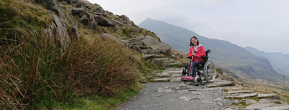
As mentioned in previous posts, the differential keeps the seat parallel to the ground as the wheels on either side go over obstacles. This is one of the main things that are drawing me to a rocker-bogie design. Ada finds it tiring in her current wheelchair when pushed along a gravel path as she bounces up and down in her seat. With caterpillar tracks (at least without further development) I think this bouncing would increase. I haven’t given it much thought yet but I imagine it would be possible to combine this differential mechanism with caterpillar tracks and have the best of both worlds.

Wheels have just come off the printer too (Ada has requested they be painted purple) and I have two more tyres to print. I’ve modified these wheels to prevent them slipping on the motor so can’t wait to see the results tomorrow.

In other news, I also built this website. Ta da! :D

More progress despite the lurgy

I’ve been feeling really run down over the last few weeks and today was no exception. Despite being ill I spent the day sat at the computer redesigning the prototype to include the differential mechanism which keeps the centre of the vehicle level, and added a seat just because it looks cool and helps to get Ada enthused. By the end of the day the new parts were being printed which also included some chunky tyres :)

Thanks to Staffert for his Bevel Gear assembly, DCHCustoms for the cool RC bucket seat and Palmiga for the OpenRC Tyres.

Not only is it alive, but it works, ish…

I woke up in the early hours of the morning and popped down stairs to see how the printers were doing. To my excitement all of the parts were finished so I sat at 2:00am constructing the prototype. Several hours later I went back to bed excited to wake up and show the family what I’d created:

It works! The prototype works! Well sort of…

The cheap motors I’m using seem to be slipping a lot which means that often the motors are turning but the wheels aren’t. There also doesn’t seem to be much grip in the tyres so often they just wheelspin instead of climbing over obstacles. I knew this was going to be an issue when I bought the motors but as a first working prototype it does at least show that the concept works.

Quick mock up using Lego

Today all those years of playing with Lego as a child was finally put to good use as I made a couple of quick mockups of possible mountain wheelchair solutions. One is the obvious choice of caterpillar tracks, the other is a rocker-bogie mechanism inspired by NASA’s Mars rovers.

I really like the simplicity of the caterpillar tracks and pushing this simple Lego model you can feel that it wants to go over obstacles. You can see that I’ve angled the front of the tracks to help it climb over larger obstacles. My main concern with this design is that it looks like it could tip over backwards quite easily.

The rocker bogie mechanism looks like it has excellent potential for overcoming obstacles but it seems finicky and things can go wrong in lots of different ways. I imagine that once there is drive to each of the wheels (as opposed to being pushed by hand) that some of these issues will be resolved.

The rocker bogie mechanism is worth exploring because even in the Lego models it looks like a comfier ride and in theory a greater ability to overcome larger obstacles. Looking in these two pictures, you can see imagine that as the caterpillar track version travels over the obstacles the seat would bounce all over the place, whereas with the rocker bogie, a differential mechanism keeps the seat level.

The following images show the differential. As the rocker on one side of the bogie tilts, the differential forces the other side in opposite direction. This results in the seat having an angle which is an average of the two sides. Most of the time then, the seat will remain parallel to the ground no matter what the wheels are doing.

Another advantage of the rocker bogie mechanism is that it removes the need for suspension. As you can see in the following images as the wheelchair comes down off an obstacle there is a gradual process and the seat remains relatively level throughout.

Whereas in the caterpillar track design the wheelchair pivots over the apex of the obstacle and then comes down with a thud.

By comparing the angle of the seat between the two designs as they step off the obstacle have left me feeling that the rocker bogie design is worth exploring first.

This page was last updated on April 18th, 2018 by .
Permalink: Tag Archive: prototype